Characteristics
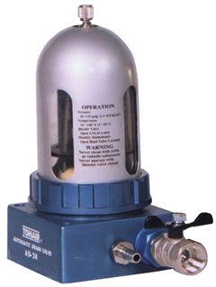
TONAIR AD-24 & AD-24H compressed air automatic drain valve is an advanced design product with international patents. The air pressure inside air compressor is connected by a guide pipe with the drain valve, the pressure relief valve on top can be used to make micro-regulation of discharge of the compressed air whereby the pressure of drain valve is lower than compressed air system force the condensate water, oily sludge and rust/particles will be emitted from compressed air system. Upon having beew pushed and squeezed continuously, water and impurities will be moved and stored below automatic drain valve; whereas the float ball will come up to switch on valve of the controller above which will take quantitative control for auto discharge and shut-off. This device will assure cleanliness inside compressed air system effectively. One more advantage of this system is that its installation will not be subject to the heights or distance, and can be installed at the desired location. The automatic drain valve can perform precise discharge of water and dirt particles without power source or other control guiding pipe.
AD-24
AD-24H
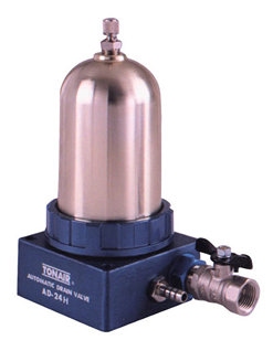
One more specially designed structure of TONAIR AD-24 & AD-24H compressed air automatic drain valve is its structure of the 3-layer segregation of air, liquid and solid, whereby the controller is not merged in waste oil and water since such fluids as wastewater does not pass the controller. Gas passage of the controller is provided with 3 filter devices to prevent the controller passage from being congested and parts can be prevented from being damaged. The controller can perform effectively without any malfunctions after having been used for a prolonged period. One more advantage of the controller is the installation of large-size cylindrical filter net and manual operated valve for discharge of waste at the bottom space in the solid structure, where water and dirt particles will flow through an inlet into the filter net, which can store lots of larger-sized scale and rust. When it becomes necessary to remove the impurities after a period of operation, time it is unnecessary to stop the operation of air compressor or release the pressure, nor use tools to remove drain valve, except easy opening of manual operated valve for removal of waste so as to discharge waste particles of rust that are accumulated in the filter in a convenient and effective manner.
Specification
| AD-24 | AD-24H | |
| Dimensions | 160m/m(L) 100m/m(W) 200m/m(H) | |
| Weight | 1.3KG | 1.4KG |
| Operating Pressure | 1.3KG/CM2~8.8KG/CM2 | 3KG/CM2~12.7/CM2 |
| Operating Temperature | 2℃~60℃ (36~140℉) | |
| Inlet | 1/2" PT (NPT) | |
| Outlet | AUTO 3/8"PT (NPT) 5/16"HOSE / MANUAL 1/2"PT(NTP) | |
| Max. drainage | 15Gal / Hr | 12Gal / Hr |
| Min. suitable air vol. | 180L/min (air compressor capacity abt 1HP) | 250L/min (air compressor capacity abt 2HP) |
| Water collection bowl | Nylon | Aluminum alloy |
- Packing: 12 pieces per carton; Gross Wt :22KGS; net Wt 21KGS
- Carton measurements: 45X34X37cm
Installation
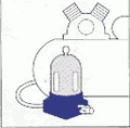
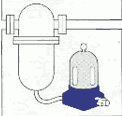
This Product may be installed into the following compressed air devices:
| Air Compressor | Separator | Air Dryer | Air Filter | Drop Leg |
 |
 |
 |
 |
 |
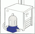
- This product may be horizontally installed in the vicinity of air compressor; in case of slanting, make sure that the gradient shall not exceed 15° and it is recommended that bolts be used for fastening.
- The compressed air inside the air compressor and large amount of condensate water shall be discharged from the lower part entirely.
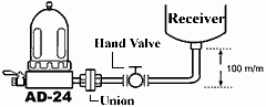
- Connect the drain valve with an air compressor.
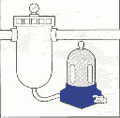
- Use 1/2” steel pipe for connection, as indicated in <Fig3.>
 <Fig3.>
- This product shall be provided with a flexible connector and a manual operated valve to offer convenient maintenance in future.
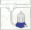
- If air compressor is installed at lower level or the location which does not offer convenient installation, use the following attachment for connection, as indicated in <Fig.4>
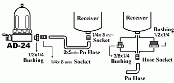 <Fig.4>
- Select one of the sockets with a dimension at 1/2”, 3/8”, 1/4 PT” for connection with air compressor.
- Cautions:
- To prevent loosening & leakage,PU hose must be inserted to bottom of the socket.
- Bushing sockets should be sealed by leak proof tape to guard against leakage.
- Operational temperature of PU pipe shall not exceed 45° C; otherwise it can damage the PU pipe. In the event where heating of the air compressor operation exceeds 45° C, use nylon copper or other pipes capable of resistance to high pressure and heating.
- When first operating the air compressor, pressure will increase gradually, whereas automatic drain valve will discharge the compressed air and excess water. When pressure exceeds 1.5kg/cm2, the internal controller will automatically shut off the valve and compressed air will not be discharged.
- Adjust the top pressure relief valve, tighten the bolt and revere it by 1/24 turn, or half grid or one grid, as indicated in <Fig.5>
 <Fig.5>
- Hence, air compressor will operate normally. If the air compressor generates condensation, it will flow through the pipe to a water bowl below. When water reaches half of float ball, the controller shall automatically open the valve to drain the condensation and it will automatically shut up upon of drainage.
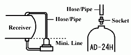
- If you prefer not to install the pressure relief valve on top of the air compressor for savings of compressed air for relief of pressure, use a guiding pipe to be connected with the air compressor to keep balance the between pressure in air compressor and drain valve; provided that the position for installation of this product shall not be highthan that of air compressor. Besides, the connection pipe will be for AD-24H only.
Basic Maintenance
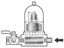
- In line with principle of differential pressure, this product was so designed as to effectively force water and dirt to a filter net below the drain valve, to assure cleaning of compressed air system.
- Upon having passed through filter net, water, waste oil and particles shall be discharged from drain connector automatically; whereas the larger-sized particles and rust shall stay at cylindrical filter, so as to avoid damage to the internal parts.
- Commensurate with quantity of dirt and rust generated in compressed air system, dirt shall be discharged by 1/2” manually opened valve at the lower end at interval of a week or a couple of months. The higher the frequency in the discharge, the higher will be the degree of cleaning.
- Quickly open the 1/2” manual-manipulated valve for 5 to 10 seconds to assure cleaning of dirt effectively, to be followed by slowly shutting-off the 1/2” valve to upgrade the control pressure.
- In case of necessity for internal cleaning, follow the sequence for dismantling and re-assembling as indicated in the following chart of parts.
- Chart of parts
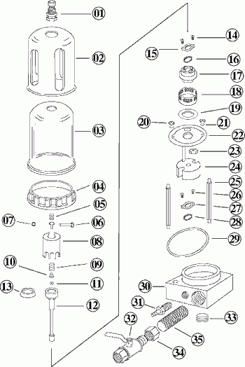
| 01. Bellder Valve | 19. Gasket |
| 02. Steel Cover | 20. Nut |
| 03. Water Bowl | 21. Spring Washer |
| 04. Screw Ring | 22. Separator |
| 05. Inlet Valve | 23. Nut |
| 06. Pin | 24. Float |
| 07. Retaining Ring | 25. Spacer |
| 08. Cylinder | 26. Screw |
| 09. Spring | 27. Ring Cover |
| 10. Filter | 28. O-Ring |
| 11. Discharge Plate | 29. PVC O-Ring |
| 12. Piston | 30. Base |
| 13. Piston Ring | 31. Barb fitting |
| 14. Screw | 32. Hand Valve |
| 15. Ring Cover | 33. Plug |
| 16. O-Ring | 34. Filter Base |
| 17. Cylinder Base | 35. Filter |
| 18. Filter | |
| Note: The material of Water Bowl (03)
AD-24: Nylon
AD-24H: Aluminum alloy, no Steel Cover (02)
|
|
Trouble Shooting
| Faults | Causes | Trouble-shooting |
|---|---|---|
| The drain system cannot drain automatically as a result of water level in excess of damper (22) |
|
|
| Continuous discharge of compressed air from drain socket (31). |
|
|
| Small amount of drops continue flow out of drain socket (31) |
|
|
| Air leakage due to PU hose broken |
|
|
| Breakage of transparent water collecting bowl (03) |
|
|
| No pressure inside drain valve. |
|
|

 English